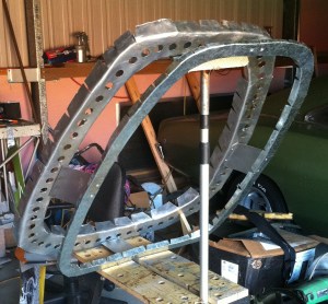
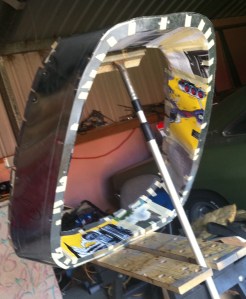
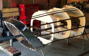
This month I’d like to share how I went about constructing the Viper nose intake nozzle and how I formed the nose section bulkeads or frames.
Using the fueselage profiles described in last month’s post, I traced the shapes on 12mm plywood sheet and cut them out using a jigsaw.
I then traced the profile onto 1.0mm sheet aluminium for the rear bulkead and allowed extra for the flange formation.
The front an rear intake nozzle bulkheads were then correctly aligned and joined.
The inner and outer skin required for the nozzle has a number of curved sections and I felt the best way to do these was to develop cardboard templates, so that I could accurately mark out the sheet aluminium.
I then used the templates to mark and cut out the outer skin from 0.5 mm sheet aluminium. These were then drilled and fitted with cleco fasteners. Clecos have been extensively used in metal aircraft construction for decades and I’ve found them excellent to work with.
I then repeated the process for the inner skin, first developing a template and then cutting and fitting the sheet aluminium.
The inner skin was then fixed in place with cleco’s.
I countersunk the rivet holes and used flathead, countersunk 3.2mm rivets to fasten the sheeting. I intend to fill these with body filler prior to paint, as the Viper has no visible rivets on the airframe except for the canopy frames. Filling countersunk rivets is common on airframes where speed and minimisation of drag are critical. P51 Mustangs, Spitfires and Me262 warbirds all had countersunk and filled panels.
I then proceeded to mark and cut out the remaining nose section bulkheads from plywood sheet. I then spent a bit of time ensuring the alignment of the bulkheads appeared accurate.
After I was satisfied with the bulkhead profile alignment, I marked out 1.0mm sheet aluminium and cut out with a jigsaw. I learned a few tricks along the way with the nozzle construction which made the remaining bulkheads much easier to form. I also cut out lightening holes with bi-metal hole saws and flanged for greater strength. And they look very cool – a must have for any airframe!
Next time I’ll detail the fitting of the bulkeads to a jig and construction of the nose section frame using stringers.


